Testing and investigation identified an unexpected over-voltage condition as the proximate cause of failure of the radar instrument portion of the Soil Moisture Active Passive mission.
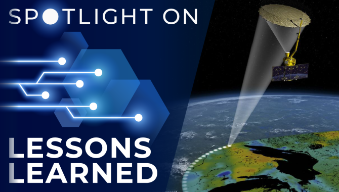
Soil Moisture Active Passive (SMAP) is an Earth-orbiting observatory designed to create global, high-resolution mapping of soil moisture and its freeze/thaw state. SMAP consists of a 3-axis stabilized spacecraft bus and a spun instrument assembly (SIA). The SMAP science instrument payload consists of an L-band radiometer and an L-band radar.
In July 2015, 208 days after launch and after completing two months of nominal on-orbit operations, the radar portion of the SMAP Radar/Radiometer instrument failed in a high-energy, proton-rich portion of the orbit called the South Atlantic Anomaly. The project team and a Failure Review Board (FRB) were initially unable to identify a single, specific proximate cause or root cause of the failure. However, additional testing conducted after completion of the FRB report revealed a likely proximate cause of the radar failure. Back voltage resulting from leakage inductance in the load transformer in the Low Voltage Power Supply (LVPS) circuit caused voltage spikes that significantly exceeded the 250 V rated voltage applied between the source and drain of the metal-oxide semiconductor field-effect transistor (MOSFET).
To verify that the anomaly could have been caused by this condition, nine power MOSFETs were tested for heavy-ion induced Single-Event Effect (SEE) failure and another nine were tested for protons using a different radiation facility. To ensure flight-like testing, both sets of tests used the SMAP LVPS breadboard assembly. Once the manufacturer’s voltage rating was exceeded during the tests, all 18 irradiated test parts exhibited catastrophic SEE identified as single-event burnout, which resulted in circuit failure.
Lesson Number: 27701
Lesson Date: March 30, 2019
Submitting Organization: Jet Propulsion Laboratory
HIGHLIGHTS
LESSONS LEARNED
- Field effect transistors (FETs) may become vulnerable to radiation damage after being subjected to an over-voltage condition — even where the drain-to-source voltage only briefly exceeds the manufacturer’s limits. When leakage inductance is present in a system, transient over-voltage conditions may result that could contribute to this susceptibility.
- Circuit design and analysis may not consider that the risk to radiation-hardened FETs from this overvoltage condition is due to SEE susceptibility (as opposed to voltage stress or other factors commonly included in circuit analysis).
RECOMMENDATIONS
- Switching voltage transients caused by leakage inductance should be characterized through simulation and test as well as protective circuity (e.g., snubbers, clamps) employed where needed.
- For circuit devices that are susceptible to SEE and are intended to be operated in a radiation environment over the course of a mission, ensure that the devices are protected from even transitory over-voltage conditions that could trigger Single-Event Burnout or Single-Event Gate Rupture.
Consult the lesson learned for complete lists.

Jonny Pellish
Credit: NASA
NASA Electronic Parts Manager / NASA Electronic Parts and Packaging Program Deputy Manager Jonny Pellish on the importance of this lesson learned:
Radiation effects induced by exposure to the natural space environment represent credible threats to every aerospace system and their constituent electrical, electronic, electromechanical, and electro-optical (EEEE) parts. Radiation effects can produce cumulative degradation leading to functional failure, as in the case of total ionizing dose (TID). They can also produce both non-destructive and destructive events following the transit of a single high-energy charged particle like a proton or heavier ion. Though single-event effects (SEE) can be locally non-destructive, triggered cascade effects unmitigated at the function or system level can still be highly disruptive, requiring power-on-reset capability, possible ground intervention, and in rare cases damage to downstream components.
Radiation hardness assurance (RHA) encompasses all activities undertaken to ensure that the electronics and materials in a space system perform to their design specifications in the context of a given mission, environment, application, and lifetime (MEAL). RHA includes environment definition, EEEE part and material selection, EEEE part and material testing, spacecraft layout and radiation-tolerant design as well as mission, system, and subsystem requirements. It must balance both design and risk trades for a MEAL within the bounds of programmatic and technical resource limitations. RHA for TID, SEE, and other radiation effects must be performed as an integral component of the overall circuit design and systems engineering process.
Radiation hardness is a multi-dimensional property of any EEEE part that describes intrinsic abilities to tolerate various radiation environments. Radiation effects concerns may be the same whether a EEEE part is Commercial-Off-The-Shelf (COTS), MIL-SPEC (e.g., governed directly by MIL-PRF-19500, MIL-PRF-38534, or MIL-PRF-38535), or subject to custom screening methodologies (e.g., NASA-screened COTS). All EEEE part variants are subject to the same radiation threats. This is an important point and indicates an increasingly complex trade space as the diversity of part grade variants continues to increase as more and more COTS devices are traded into system designs alongside their MIL-SPEC counterparts. As mentioned previously, SEE consequences range from recoverable errors to catastrophic failure. Like other random faults, SEE can be mitigated with focused circuit design practices at the device, card, and/or system level.
In the case of the SMAP radar failure, the proximate cause was an unexpected over-voltage condition in a radar Low Voltage Power Supply (LVPS) circuit that triggered a known device sensitivity to destructive SEE in a power metal-oxide semiconductor field-effect transistor (MOSFET). The destructive SEE failure occurred in a MIL-PRF-19500 radiation-hardened 250 V power MOSFET. This was not a COTS or NASA-screened COTS device and illustrates the importance of performing RHA as an integral component of the overall device selection, circuit design, and systems engineering process. It is essential to understand the radiation hardness of EEEE parts in avionics and instrument systems, which is usually a combination of analysis and testing. However, it is also critical to understand the manufacturer-specified performance limits of EEEE parts, which in this case included both electrical and radiation safe operating areas.
While the SMAP failure and lesson learned highlighted the likely impact of a destructive SEE, the intrinsic radiation hardness of the power MOSFET in question wasn’t the problem. The failure stemmed from a violation of the data sheet-defined safe operating area by electrical voltage transients unrelated to radiation event stimuli. Manufacturer performance limits are not always sufficient for a given MEAL, especially with respect to radiation effects, but accounting for them is necessary as part of good design practices to ensure mission safety and success.
Related Resources
Radiation Single Event Effects (SEE) Impact on Complex Avionics Architecture Reliability – NTRS
Avionics Radiation Hardness Assurance (RHA) Guidelines – NTRS
Spotlight on Lessons Learned is a monthly series of articles featuring a valuable lesson along with perspective from a NASA technical expert on why the lesson is important. The full lessons are publicly available in NASA’s Lessons Learned Information System (LLIS).
If you have a favorite NASA lesson learned that belongs in the spotlight, please contact us and be sure to include the LLIS Lesson Number.


